1. Provided with RS485 or RS232 communication function, standard Modbus adopted to communicate with upper computer.
2. Analogue quantity output, 0~5 V/ 0~10 V/ 4~20 mA.
3. Applicable to detect or measure.
4. Ultra-long detection distance and easy to align correctly.
5. High in accuracy and good in performance.
1. Working Principle
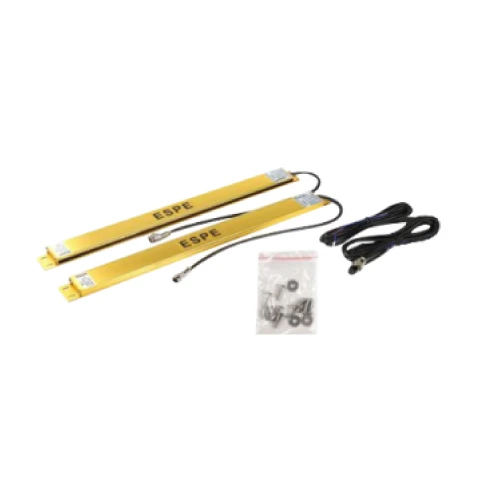
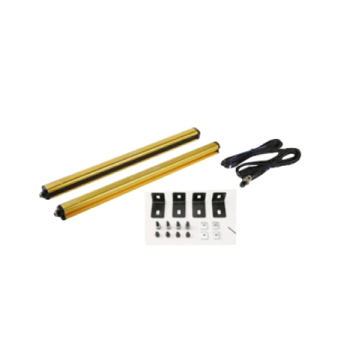
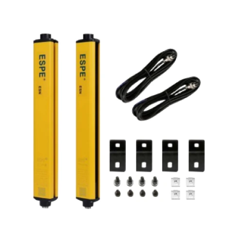
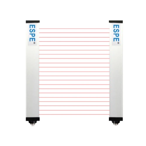
ESCL series measuring & detection light curtain consists of emitter and receiver. The emitter emits the light directly to the receiver and form the light curtain system. When an opaque object enters the sensing area of the light curtain, a part of light beams will be interrupted and it cause the receiver can’t receive the due light. ESCL series measuring & detection light curtain adopts synchronous scanning to identify the interrupted channels.
Firstly, a emitter channel transmits a optic pulse and the due receiver will come to receiver the optic pulse. When the reception finishes, it will start the scanning of next channel and until the completion of all the scanning. When a scanning cycle finishes, the system will record in which channel light is through and in which channel light is interrupted and then outputs a signal according to systematic definition. The signal can be analog quantity signal or digital quantity signal
2. Control Output Method
a. On-off output: NPN output.
b. Internal(or external) regulating switch or remote controller can be used to set aspecific number of light beams interrupted, only with which there will be output of signal from the light curtain.
c. When applied on void detection, there will be output signal only when any or morelight beams pass through.
d. When Eight-bit Binary adopted, the light curtain will follow Eight-bit Binary to proceed outputof interrupted channels.
e. Analog quantity signal output: 4-20mA、1-5VDC、0-5VDC、0-10VDC, can be connectedwith upper computer or other data gathering system
f.Provided with RS485 orRS232 communication function, standard Modbus adopted to communicate with upper computer.
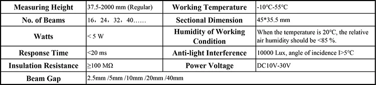
3. Technical parameters
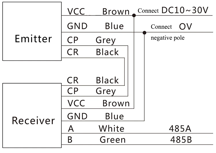
4. Wire Connection Diagram
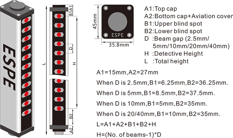
5. Dimension Diagram
6. Model Selection